


Mini Mill Modifications
There are many power tools used in modelers shop but there are two which I believe are the best bang for bucks: mini lathe and mini mill. I would not be able even to think about some projects without these two.
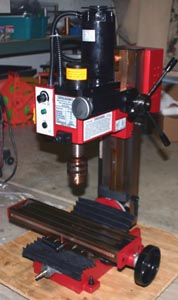 | First I bought mini lathe form Homier online store. It was one of many variation of Sieg 7x12 machines. Few years later I got Mini Mill from Harbor Freight - a variation of Sieg X2 mill. These two machines are very good when tuned well. I was able to achieve the precision of 0.001inch what is enough for my needs. When the mill arrived to my shop it was mostly assembled but I decides to take it apart, clean, lubricate and adjust the way I wanted. It paid off with smooth run and almost no lash. At the same time I replaced X and Y screws with metric ones. Very soon I found that there are few "must have" additions when using mill: -Set of collets. Supplied drill chuck is good for drilling, but not precise enough for milling. In order to achieve good precision the mill must be mounted very precise, true and as close to the head as possible. This is how you do it with collet. - Good milling vise. This is obvious. Part for milling must be mounted solid to the table. there is nothing better and convenient than good quality vise. - Rotary table with lathe chuck. I have not discovered all possibilities of that tool, but it would be not possible to make variable pitch prop hub without that. The next two additions were more from "convenience" area than "must have". However after using mill for some time I'm sure this is the money and time well spent. |
Even my mill was converted to metric units it was still a lot of work to calculate table travel to "turns on knobs". Metric version is quite weird as one turn on the knob moves the table by 1.5mm and the scale on the knob is divided into 75 marks (0.02mm travel per mark on the knob). So for example 2mm travel would be represented by 100 marks which is one full turn plus 25 marks from the second turn. It was easy to make a mistake especially when I used "imperial size" end mills.
I have researched many options for implementing DRO on this machine. There are some solutions with digital scales, that look like modified calipers (you will need to read the display mounted on the scale) or quite expensive DRO sets with computerized display that were mostly designed for bigger machines (SIEG X3 mill or bigger). I decided to use a solution someway between these two.
There is a company Anytime Tools located in California which is also selling on eBay different sizes of DRO scales with remote mounted display. That was exactly what I needed. I used three scales: 12 inch for X, 6 inch for Y and 12 inches for Z what cost me total less than 150 dollars. Mounting these scales on the mill was straight forward using original brackets supplied with scales. The only difficult part was making a spacers for Y-scale mounting. The side of the mill is rough and not even, just as it came form the cast. To assure that the scale is exactly parallel to the Y-axis table these spacers had to be quite odd shape. Here are some pictures of the mill equipped with this cheap DRO.


The only bad thing about this solution is that the Y-axis movement is shorter by about 1/2 inch because the back of X-axis scale is touching the column when the table is pushed all the way in. After using these scales for over a year they are sill working without any problems.
In order to mount Z-axis scale I had to remove the original torsion-arm counterweight. The original solution in this mill was not the best anyway as the design shorten the Z-axis travel and it did not counter-balance the head the same in all positions. I decided to make my own counterweight solution.
There is a commercial "upgrade-kit" available on the market like Air Spring Conversion Kit from LittleMachineShop.com. Actually it is the old design from Sieg mini mill which for whatever reasons was discontinued by original manufacturer some time ago. Using gas spring assured the same force supporting the weight of mill's head along the entire Z-axis travel. However the one thing I did not like in this solution was that it increased the total height of the machine. And it was not "elegant" for my taste.
After some thinking and calculations I came out with simple, but effective and elegant solution. I used two 6-inch travel 30lb force gas springs (bought from Enco) mounted inside the column and two pulleys. 1/16 stainless steel cable guided through pulleys is supporting the mill's head. For pulleys I bought rollers used in sliding doors from local hardware store. These rollers have ball bearings inside which provide low friction rotation. The following pictures should explain how the whole solution works.


The good thing about this solution is that gas springs are mounted with cylinder-up (the best mounting for keeping seals lubricated) and being hidden inside the column they are protected form saw dust. And it is elegant. Now because for Z-axis DRO I used 12 inch scale I can use full head's travel - almost 12 inches. The lowest position is where end mill mounted on R8 collet can dig into the table and the highest position is where the head goes just a bit above the column.


There are some additional information regarding counterweight solution.
The gas springs I used from Enco had part number 319-4367 (30 LBS. 6" STROKE GAS SPRING GGS23). When I got my gas springs I noticed that having the same part number they had different model numbers (shown on the label). The length was different by about 1/4 inch. After I contacted Enco and explained that I need two identical parts, they send me matching gas spring free of charge.


On the first and the second picture you can see a piece of wire that is preventing the cable from slipping of the roller. Without that it is impossible to assembly the whole thing inside the column. I will add the same wire to protect the cable from slipping of the upper roller. When the mill is not used for a longer time the gas spring "locks in" and and if I move the head upward the gas spring starts expanding with a split second delay. If I move the head rapidly the cable will loose a tension for a split of second and it is enough to jump of the roller. It is only happening if the mill is not used for few days or more. For now I start work by moving the head down to "loosen up" gas springs.
These are the steps how the whole thing is assembled:
1. Put the whole unit together without the cable
2. Hook up one end of the cable to the mill's head
3. Run the cable through the unit - the loose end should exit through the hole between two black screws (as shown on the picture 5)
4. Mount the unit inside the column (securing all screws)
5. With mill's head all the way in the upper position (locked) tighten the cable and pull it just a bit to build the tension (where gas springs start to squeeze and will support the head.
6. Secure the loose end of the cable using two black screws (as shown on the picture 9 and picture 10)
7. Unlock the head and tun it up and down to few times make sure it is balanced. It was balanced in my mill.
I weighted the head and it is about 33 lb (not including chuck or collet). I measured also the force of this 30lb gas spring. From the beginning to the end the force was between 35 and 40lb. I guess it will leak some gas in years and may reduce the force to 30+ lb.
2011-04-28
The next addition to my mill was installing belt drive kit from Little Machine Shop.This was the easiest modification ever. The kit has excellent design and prime quality of machining. All parts are included in the kit and the step-by-step instruction is clear and very logical. Installing the kit took 15 minutes.I am very pleased with that product.
After conversion there were two major improvements. First of all the noise from mill's gearbox has been eliminated. I realized now how noisy the mill was. Now the only noise (besides cutting the metal) is a soft whining of brushed motor. The second improvement important for me was the increase of the head speed. At Low setting the head speed increased from 900 rpm to 1525 rpm. On High position the head speed increased from 2500rpm to 4150rpm. It is a little less than advertised 1700/4300rpm but it is probably because the motor in my mill has slower rpm slower than in a "test mill". I would recommend that upgrade to everybody who is still running their X2 mill with original gearbox. It is worth the price.


